POSTS
LED Strip Audio Visualizer

Description
This project uses an Arduino MEGA 2560 to continuously perform an FFT on an audio signal and display it on an LED strip. It can also adjust the volume of my speakers with a remote control. The remote works reliably up to about 40 feet away (through 1-2 walls).
Visualizer
The visualizer part of the code uses Tom Roberts’ fixed-point FFT library and displays the result on an Adafruit DotStar LED strip. The code that invokes the FFT and calculates the RGB LED strip values is in main.cpp. A timer interrupt causes the ADC to push audio samples into a circular queue at a regular interval. This queue is copied into an array and an in-place FFT performed on that in a busy loop.
Volume Control
The speakers in my apartment have a volume knob which uses a rotary encoder and pull-up resistors. I bought the speakers from Goodwill so they did not come with a remote. The way this device controls the volume is by connecting to the pins on the encoder and controlling them in a wired-AND fashion. By emulating the sequence of signals an encoder makes with two of the Arduino’s digital pins, it is possible to “trick” the speakers into thinking the volume knob is being turned. It is worth noting that because this uses wired-AND, volume control only works when the physical volume knob is at a position that leaves both encoder contacts open. If this is not the case, full encoder rotation cannot be emulated. Because of this, there is a command that can be invoked over UART by sending a question mark (?) character to the device, or by pushing the reset button on the remote, which will query the position of the knob and display it on the LED strip. If it is in the correct position, the leftmost LED will light up green and the two LEDs to the right of it (indicating the encoder contact logic levels) will be white for about 100ms. If this is not the case, the LED will light up red. This command also resets the state of the two pins connected to the encoder to the disconnected state, meaning you can use the physical knob like normal after invoking it. The code that controls the encoder pins is in volume.h.
Remote
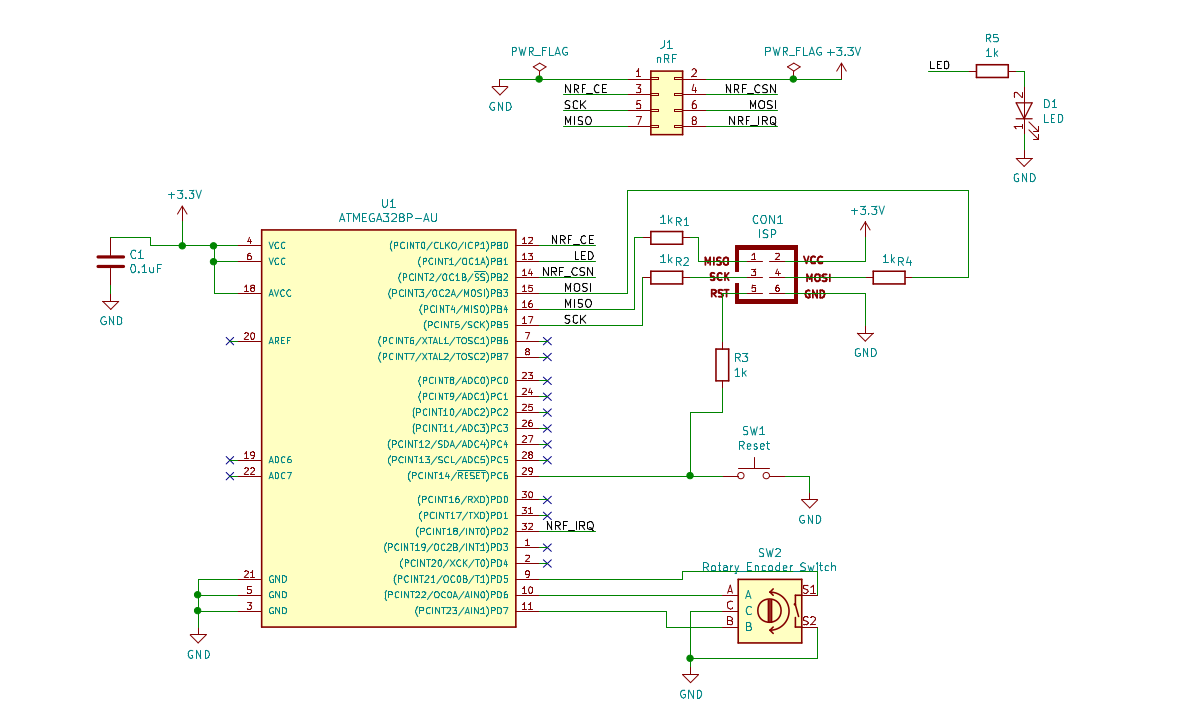
Volume control wouldn’t be very useful if you still had to walk to the speakers to change it. The volume can be controlled either by sending the device characters over UART (38400 baud, ‘+’ for volume up, ‘-’ for volume down), or by using the knob on a remote control. The remote uses an nRF24L01+ transciever module and is controlled by an ATMega328p. The remote is simple to use. Turning the knob clockwise increases the volume and counter-clockwise decreases it. After a few seconds of inactivity the remote returns to a low-power sleep mode that draws about 1.5 microamps when using a 3V battery. Turning the knob fires a pin-change interrupt that wakes it from sleep. With normal usage, the remote batteries should last several months or longer. All of the code for the remote is in a subdirectory of the github repo. Code for the nRF module is partially based on tmrh20’s RF24 library, but was written almost entirely from scratch using the nRF datasheet. For the purpose of interference hunting, the LED on Pin 13 of the arduino will light up when interference is detected in the carrier frequency band (2,476 MHz).
Schematics
So far I have only made a schematic for the remote. Here it is.

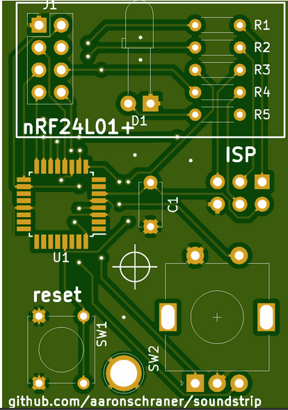
I also have a PCB design in the works. Here is a preview.

Pin connections for both the remote and the base station are easy to find in their respective main.cpp’s.
Software
All of the software is posted on github.
Issues
- Audio input does not have an anti-aliasing filter
- Still need to make PCB for base station
- Audio connector
Fixed issue: weird current draw behavior
